76 CIVIL WORKS GUIDELINES FOR MICRO-HYDROPOWER IN NEPAL
The pipe should be able to divert both the incoming flow and
the water volume in the basin, thus emptying it. This is based
on the following equations:
1.5Qdesign = CA hbasin + hflush
or, Qdesign = CA hflush
where:
Qdesign is the design flow. Qdesign is multiplied by 1.5 in the first
equation to ensure that there is a draw down in the water
level inside the basin during flushing (i.e., both the incoming
flow and the flow in the basin can be drained).
C is the orifice coefficient = 2.76 (applies only where the
total pipe length is less than 6 m).
hbasin is the depth of water in the basin during the design flow
prior to flushing.
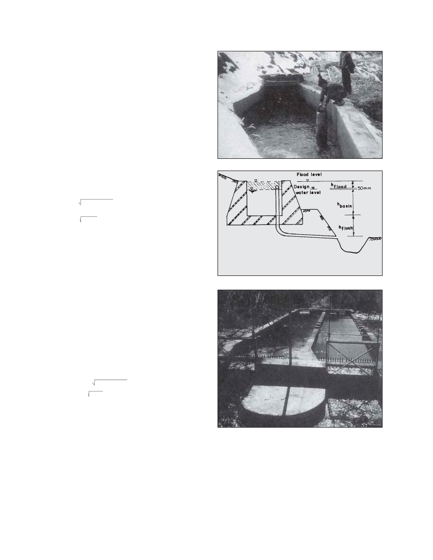
hflush is the flushing head when basin is empty. This is the
difference in level between the floor of the basin and the
flush pipe outlet as can be seen in Figure 5.6
A is the area of the pipe section.
The second equation ensures that the design flow can be
discharged through the system when the basin is empty. It is
important to check this condition especially if the hflush is low.
d = ( 6Qdesign / ΠC hbasin + hflush )
or,d = (4Qdesign / Π hflush )
In terms of the pipe diameter, the above two equations can be
rewritten as follows:
Note that these equations assume that there is free pipe flow
at the outlet and the pipe diameter is constant (vertical and
horizontal pipes of the system have the same diameter).
All of the above three equations should be used to size the
diameter of the flush pipe. The pipe should be sized using
the equation that results in the largest diameter. If the total
pipe length is more than 6 m, the flow should be calculated
using the guidelines given in Chapter 4.
5.3.8 OTHER CONSIDERATIONS
Spillway requirement
If excess flows can not be spilled from the upstream headrace
portion such as due to lack of a suitable area (or if a pipe is
used), a spillway should also be incorporated at the settling
basin. The spillway should be sized to spill the entire flow
expected during the high flow season. This is because the
plant may need to be shut during high flows for repair work.
The spillway should be located upstream of the basin to avoid
excess flow (and sediment) through the basin. Note that the
design of spillways was covered in Chapter 4.
However, in the case where there is a vertical flush pipe sized to
divert the expected high flows, a separate spillway is not necessary.
Cover
Sometimes there can also be site specific considerations that
need to be addressed during the design of the settling basin.
Photo 5.5 Settling basin at Jharkot
Figure 5.6 Vertical flush pipe section in a settling basin
Photo 5.6 Salleri Chialsa settling basin
For example, the Ghandruk settling basin is located in a forest
area and large tree leaves were constantly blocking the
trashrack. This problem was overcome by placing wire mesh
over the basin as can be seen in Photograph 5.7.
Sluice gate
Another conventional method of flushing includes the use of
sluicing gates. This is more common in mini- and large
hydropower schemes. In this system, gates are lifted either
manually or mechanically, to drain the basin. The Salleri